Intelligent power management for Raspberry Pi![]()
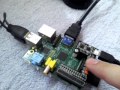
![Assembled board]()
Project Summary![]()
RPi Power Management problem
RPi is usually powered by wall power supply adapter with +5VDC/1A output. Once power cord is plugged in, RPi starts booting and after while Linux desktop appears. Once 'System Shutdown' signal from Linux is sent shutdown routine will be activated and computer goes into stand-by mode after some time. Little power is still consumed in stand-by mode. Keyboard and/or mouse and monitor must be connected to the RPi to properly handle shutdown. To boot RPi again, power must be toggled OFF-ON manually. Therefore manual power switch must be installed or 'adapter plug/unplug' must be performed to boot system again. And this is small flaw in current RPi configuration....
Linux Boot/Shutdown sequence
Linux as almost all others operation systems does not like hot unplug of power supply. During this event loss of data or data corruption may occur. Thus is strongly recommended to perform proper Boot/Shutdown sequence via Linux 'System shutdown' command. This task is easy once monitor, keyboard and/or mouse are present. But, if RPi is used as embedded computer, this operation become very difficult.
RPi ATX Power Supply
Problem can be easily solved by using miniature RPi ATX power supply snap-in board. This simple piece of hardware is equipped with microcontroller, solid state overcurrent protected switch, LED indicators and push button. Original Mini USB power cable is connected to ATX-PS board instead of RPi itself. When push button is pressed for time period longer than 2s, RPi will power-up and boot into Linux environment. If user decides to shutdown RPi, push button needs to be pressed for 2s again. LED indicator starts toggle and 'System Shutdown' signal will be send to Linux. After RPi goes to Stand-by mode, power supply is disconnected and RPi board is completely power off. Frozen RPi can be restarted by pressing push button longer than 5s.
This 'One button' solution has obvious benefits once RPi is used as embedded computer or even if user is lazy to issue Shutdown command via mouse or keyboard. There is also additional 2 pin connector for external +5VDC power supply connection. Why? Because I am not big fan of USB-Micro connectors and want to have option for connection of another power source as well.
RPi ATX-PS installation
ATX-PS is snap-in and GO! board with 26way connector on one side and fixing hole 3.2mm on other side. One M3 bolt and 10mm spacer are holding board in place. There is possibility to add (solder) additional 26way connector with 1:1 connection in case user wants to preserve all extension GPIO pins for his own application. There is only one restriction in this setup. Pin GPIO4 – P7 is used for system shutdown and can not be used by other user applications. See pictures Gallery on top of this page.
Who We Are & What We Do![]()
We are bunch of electronics enthusiast, engineers and hobbyist who likes everyday chalenges and love to solve problems. We are trying to promote control electronics to mases and support tallented kids with their projects.
Based in Singapore we have access to Hi-tech technology and manufacturing facilities. Therefore there is no problem to arrange mass production of useful devices and distribute it worldwide. We hope, RPi-ATX-PS will be one of them.
What We Need![]()
There has been few attempts to develop power management board for Raspberry Pi. All of them are FIY (finish it yourself) devices and they are not so user friendly.
Therefore we have developed our own RPi-ATX-PS board for our own use. But we got some additional demand from other folks which find this device usefull. There exist reasonable assumption, that more people worldwide will like our solution and we want to give a shot.
To manufacture this little board as cheap as possible, larger quantity must be ordered. According to our calculation, $2500 is minimum amount to send order to manufacturer, set up machines, manufacture one batch and pay all logistic fee and commissioning time. And this is what we need money for...
If you will back up this project three messages from you will be send out:
- I like this project
- I find it useful
- I want to buy this device
based on your feedback, we will get idea for future manufacturing...
What You Get![]()
Our plan is as follows:
For every $15 of pledge you will get one fully assembled, tested and ready to use ATX-PS as per small top picture
- If your pledge will cover 1 device you have to add 5$ to cover delivery charge worldwide total pledge $15 + $5 = $20
- If your pledge will cover 2 devices you have to add 5$ to cover delivery charge worldwide total pledge 2x$15 + $5 = $35
- If your pledge will cover 3 or more devices you will get 3 or more devices $15 each with free delivery worldwide.
If total amount funded will exceed $5000 there will be free delivery charge world wide for everybody who will order more than one piece of ATP-PS !
Final Products Specification & Software![]()
Final PCB will contain branded components and will be gold plated. PCB on picture is tin plated. PCB color will be Black or Green and decision about what color will be used will be made by You on our forum later on.
- power input Micro USB or 2.54mm header
- input voltage max 5.5V
- overcurrent protection 1.5A (very handy if something goes wrong with RPi or periphery)
- status LED indicator
- additional header for GPIO connections available
Simple script issuing command ‘Shutdown –h now’ is monitoring ATX-PS board and once power off request from board is given, command will be executed. Short script uses native Linux commands and standard memory access. No Python interpreter or additional libraries like WiringPI, BCM2835 or others are needed. Script and detailed instructions how to install it will be available on website...
![]()
Thank you for your consideration...![]()