Arduissimo
Arduissimo is a MultiCore Arduino
Project. It is based on the Low Cost FPGA Arduino Board – called
“Morpheus I”, which is the central element of this
project:
![]()
The following picture gives an overview
of how to use it:
![]()
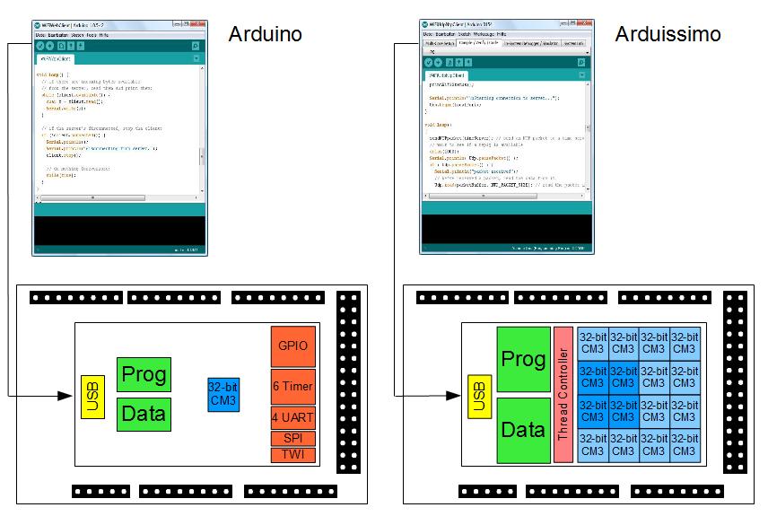
An Arduino board usually has a chip
with one processor, program and data memory and a set of peripherals.
You can program it using the Arduino IDE or other IDEs like the Atmel
Studio and you can use the Arduino language or other languages like
C++. You download the program through the USB interface for example.
This is also true for this project. You
can use the enhanced Arduino IDE called the Arduissimo IDE or
alternatives like the Atmel Studio and languages like the Arduino
language or C++ as well. The difference is, that you now have 16
processors available and more program and data memory to run your
code. The system has a maximum system performance of 166MHz, which
means that when you use 5 processors, that each one of them is
running at 33.2MHz. The system boots from the SD-card when applied.
The Arduino DUE is based on an ARM
Cortex M3 CPU (“CM3”). This project is also based on a Cortex M3
compatible CPU.
But the performance increase and the
multicore solution are not the only new aspects here. The cool thing
is, that the system is optimized to execute virtual peripherals.
Virtual peripherals provide the functionality of common peripherals
like PWMs, serial interfaces etc., but they only exists as software
code.
IDE
![]()
If you want to use the Arduino IDE –
instead of Atmel Studio – then, don't worry. You can assign
individual loops to individual processors or leave the multicore
handling to the compiler. It is as simple as using the original
Arduino IDE.
![]()
An additional frame lets you setup the
project directory and structure. You can also define a set of sketch
files for your project.
Virtual Peripherals
Virtual Peripherals replace fixed
hardware peripherals with their functional counterparts in software
using software code and standard GPIOs (General Purpose Inputs and
Outputs). The concept of Virtual Peripherals is best explained with
an example:
![]()
The picture shows how signals of a
simple serial interface (cs (chip select), clk, data) change over
time to transmit data. It becomes clear, that most of the time, the
signals remain constant. Only at specific time-points they alternate
their value. This is indicated with the little vertical arrows at the
timeline arrow. These actions can be handled by a little software
threads that modify the right signals at the right GPIOs at the right
time.
This method can become very timing
critical, when you need multiple (many) peripherals, but you only
have one processor for it (and all the rest). This is where the
MultiCore solution of this project is perfect. I has many processors
available which quickly execute a thread when needed and then fall
into waiting mode again. There is no fixed relation between a series
of threads for one virtual peripheral and one processor. Threads are
executed on any of the available processors at a given time-point.
![]()
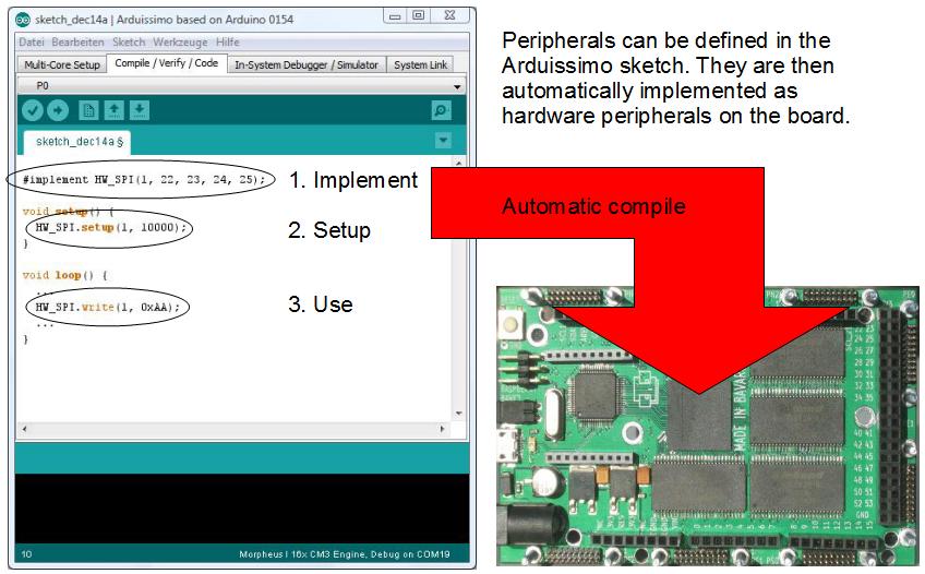
The Arduissimo project fully supports
Virtual Peripherals. The Arduissimo board has 99 General Purpose
IOs. This allows you to use an almost unlimited number of PWMs, I2C,
SPI etc. You can still use the standard Arduino Peripherals (for code
compatibility for instance) and you can also use common predefined
Virtual Peripherals as easy as writing Arduino code in the Arduissimo
IDE. It is also possible to modify existing Virtual Peripherals or
define new Virtual Peripherals. You can also use a more professional
IDE like the Atmel Studio and other languages like C++ for it, as
shown in the next picture.
Maybe this MultiCore project optimized
for the embedded world, enabling Virtual Peripherals and using
standard languages and programming flows is one way how the future
might look like. So be one of the very first ones to support it.
RISC-V Version
(NEW)
The project supports the recently
announced RISC-V processor. A 16-core version is running on the
Morpheus I board at 166MHz (3-stage) and can be used for your project
using the RISC-V compiler flow.
[riscv.org:] “RISC-V (pronounced
"risk-five") is a new instruction set architecture (ISA)
that was originally designed to support computer architecture
research and education, which we now hope will become a standard open
architecture for industry implementations. RISC-V was originally
developed in the Computer Science Division of the EECS Department at
the University of California, Berkeley.”
Processing for
FPGAs (NEW)
[wikipedia:] “Processing is an
open source programming language and integrated development
environment (IDE) built for the electronic arts, new media art, and
visual design communities with the purpose of teaching the
fundamentals of computer programming in a visual context, and to
serve as the foundation for electronic sketchbooks.”
The Arduino folks adapted processing
for the Arduino IDE. This project now enhanced this IDE by
incorporating the FPGA compile flow. This allows you to define any
peripheral of your choice and to use it on the Morpheus I board.
![]()
The FPGA compile flow is incremental,
which means that the design only changes when the peripherals are
modified. The implementation is based on a single Cortex M3
compatible CPU design.
Emulator and
Virtual Prototyping
The Arduissimo project provides an
emulator. An overview of the GUI gives the next picture.
![]()
With this emulator you can debug your
Arduissimo code. It lets you set breakpoints and lets you step
through the code. You can check out special function register values
and display port waveforms. Also a stimulie pattern can be defined.
The emulator is open source java code,
so anybody can modify and improve ;-) it.
![]()
Sometimes emulators are limited. This
is why this project supports the idea of virtual prototyping. The
emulator is based on a cycle accurate C model which is automatically
derived from the MultiCore Arduissimo design. This cycle accurate C
model can now be embedded in your simulation model of your robot or
environment model. A demo project shows you how.
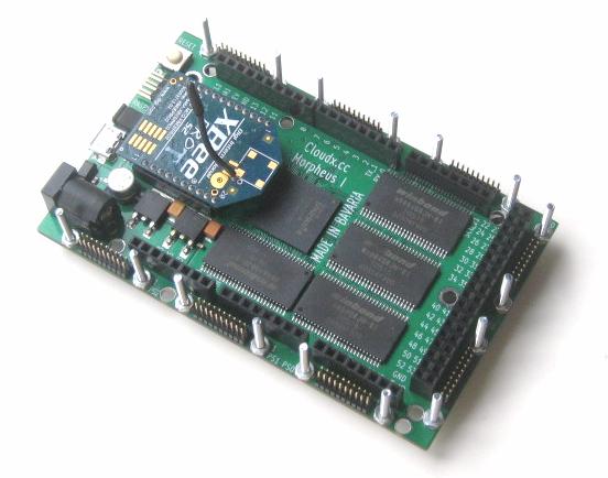
Low Cost FPGA
Arduino (Morpheus I) Board
Finally, here is the specification of
the magic Morpheus I board we are talking about all the time.
Specification
details:
Size
98.5 mm x 60 mm
Power supply: DC 3.3V - 15V
Xilinx Spartan-6
LX25 CSG326 -2 (NEW)
ADC, 16-channel, 10-bit, ESD
protection (NEW)
EEprom 4MB for configuration file and user data
High Speed USB, FTDI HS2232HL (13 pins for “245 fifo sync”
connected to the
FPGA)
SDRAM Interface 1: 6x 8MB (48MB),
166MHz, 32-bit data width
SDRAM Interface 2: 1x 8MBit, 166MHz,
16-bit data width
microSD-Card holder (6 pins connected to
FPGA)
99 IOs:
3 IOs: 2,54mm header (e.g. Raspberry Pi)
2 IOs: 2mm header (e.g. Xbee,
Bluetooth Bee)
72 IOs: Arduino Mega footprint
(72 IOs shared with uPlug)
94 IOs: 8 uPlug connector slots (72
IOs shared with Arduino Mega) with 24
LVDS pairs of equal length
(24 IOs shared with Arduino Mega)
50MHz oscillator
Reset
switch
One magic green LED
Power jack connector 2.1mm/5.5mm
Jumper
for Bank3 VCC input
4 nice bumpers
This
picture shows the front and the backside:
![]()
You
can plug in a Bluetooth module:
![]()
or
an
Xbee
module:
![]()
Raspberry Pi Bridge
![]()
There are mounting holes to place the
Morpheus I board on top of your old Raspberry Pi or the new Raspberry
Pi B+ Module. With the right connectors you can use one of the serial
interfaces or the USB interface. There is also an Arduissimo library
available so that they can nicely talk to each other via SPI or USB.
(Picture shows a slightly older version of the Morpheus I board.)
![]()
In
other words, your Raspberry Pi (B+) now has a flexible and large
number of peripherals, something you might have already dreamed of.
uPlug
(an outlook)
You
might have wondered what these extra headers and screws are for. They
are part of a Plug and Play system called uPlug, which is outside the
scope of this campaign, but maybe subject of the next one.
![]()
You can plug in various modules. This
picture shows an example you could use in your next drone project. It
has a video in, Xbee,
a temperature and humidity sensor, a navigation switch, drivers for
servos and motors, a GPS module, a Wifi module, LEDs and keys, an SD
Card holder for your flight data for instance and a 3-axis
accelerometer and a 3-axis gyro.
![]()
With
this example you can control your little robotic car. It has a
bluetooth module, USB master interface to control other devices, a
DAC, control modules for a stepper motors, DC motors and servos. It
also shows loudspeaker, display, PMOD, Poti, LEDs and Key modules.
And everything on top of an Raspberry Pi.
![]()
With
the new High Speed IO channels and a few new uPlug modules, the
Morpheus I board can be used for video processing. The interfaces
allow conversion to/from HDMI, DVI, DSI, Raspberry Pi Cam, PAL, VGA,
...
The Morpheus I for FPGA nerds
Evaluation Board:
The Morpheus I board can
also be used as a nice FPGA evaluation board. The user can download
his own FPGA configuration file through the USB interface. With an
additional adapter board, the JTAG pins can also be accessed when a
Xilinx
download cable should be used.
Logic Analyzer:
The 48MB 166MHz 32-bit SDRAM
memory and 8MB 166MHz 16-bit SDRAM memory combined with the HS-USB
interface make this board ideal to be used as a logic analyzer.
OpenCores Remap:
All uPlug boards can be used with it
and some SoCs from opencores – like the MSP430, ARMs or the
OpenRisc1200 - are remapped on this board and will be released as
open source.
System Configurator:
The System Configurator helps you to
download any bitfile to the Morpheus I. It also lets you define you
SoC to be mapped on the Morpheus I. This also includes customer
peripherals. It does the complete compiling and tool handling for
you. Since there is still space available in the MultiCore Arduino
design, it allows you to add customer logic to the Arduissimo
project.
![]()
Last but not least, an FPGA nerd can
also combine the Morpheus I with a standard Arduino and associated
modules. This picture shows a possible video frame grabber. The video
input stream is decoded into digital signals using a uPlug module,
the FPGA handles the video bitstream and might use the memories for
data storage. The communication to the Arduino Due can be based on
any of the serial interfaces for instances. Still there are plenty of
IOs available on the Morpheus I and of the Arduino Due.
Motivation
The motivation for this project is the
realization of an idea I had as a student. This idea multiplies the
functionality of a design – like the one of a Multi-Processor for
example – BUT on a very much reduced area. I was certainly not the
only one having this idea, but I had a lot of fun to continue working
on this technique and I think it can be very useful in today's
embedded world.
I call this further developed
technique System Hyper Pipelining (SHP). This project is all about
SHP, and instead of defining yet another evaluation board and
compiler flow etc., I made everything Arduino compatible and created
an Arduino board with an FPGA on it.
I programmed the FPGA that it provides
now 16 Arduino processors - here Cortex M3 compatible processors - using SHP technology.
Although I think that it is really cool
to run more than one processor on a very small device, and I'm very
proud to demonstrate it, I thought I needed something even more
useful to convince you guys. So I developed the concept of virtual
peripherals on top of it. Almost all “embedded” programmer
emulated any kind of interface already on a CPU and the concept of
virtual peripherals is certainly not new, but when you combine it
with System Hyper Pipelining, it can be very efficient.
So this project is all about some ideas
and about the right mix of various technologies. With this project I
want do demonstrate, that you can have a very efficient SHP-based
MultiCore solution already on an FPGA and that you as an user can
really benefit from it. So once the system is field proven then we
can think about making an ASIC out of it. Then it will be even faster
and more cost efficient.
Why Crowdfunding ?
The Morpheus I board can only be sold if the price is right.
This can only be achieved when a minimum of 300 pieces are
manufactured. To place an order of 300 pieces, I need your help by
supporting this crowdfunding project.
Price
The
price of the board is fair:
It
is 84 € for the Indiegogo campaign (including German/EU VAT tax and EU wide shipping).
The
hardware can be compared to the “Spartan 6 LX9
Microboard, MicroBlaze” from Xilinx,
which costs me 91,90 € when I buy it at RS-online today (including
German VAT tax and free shipping). The Morpheus I board is based on
an LX25.
Shipping
All
boards come in a nice Soft-Pac.
![]()
Shipping
costs are 7€. Same for national (Germany) and international bakers.
Schedule
This schedule is based on worst case
estimations. Due to the relative high investment I planned 1 round
of prototypes and a relatively long time for assembly and shipping.
15.2. Order
prototypes from manufacturer (assembly and shipping time: 35 days)
22.3 Test
prototypes (7 days)
29.3 Order final
product from manufacturer (assembly and shipping time: 42 days)
8.5 Test and
post-assemble final product (10 days)
18.5 Shipping
26.5 Delivery
If everything goes well and only one
round of prototyping is needed, boards arrive on the 26th May 2015.
Clarification
An
FPGA is used, but no synthesis is needed for Arduissimo: For the
Arduissimo solution a “frozen” design is used, means that it is
not changed by the Arduissimo user and it will only be changed when a
bug is found. Still the nerdy Arduissimo user can add customer
designs of use the FPGA entirely for a new design. Only then
synthesis is needed.
Virtual
Peripherals: It is not true that one processor executes one
peripheral, so that the numbers of virtual peripherals are limited.
The algorithm of a Virtual Peripheral is sliced into individual
threads. A thread is then executed on the next available processor.
A Virtual Peripheral does not occupy processor resources when nothing
needs to be done.
Limitation
The
Virtual Peripherals do not support high speed peripherals like
Gigabit Ethernet etc. It is fast enough to drive servos, motors,
I2Cs, SPIs and related protocols below the range of 10MHz.
Risk
The Morpheus I board did go through
several versions throughout the last years. The board will go through
further testing throughout the crowdfunding phase. The crowdfunding
goal and schedule covers 1 prototype and testing phases. I would
consider the risk that the boards don't work as low.
The electronic parts of the Morpheus I
are very common standard parts. I don't think that any of these will
be discontinued by the manufacturer.
The Arduissimo FPGA design and the
Arduissimo IDE work. Bugs can be cleared by modifying the source
code.
Thank You
Thank you for reading the story of this
crowdfunding campaign. If you think that MultiCore Programing and
Virtual Peripherals can be a lot of fun, then please become a
supporter and help us that this project can be realized. Thanks you
so much, again.